Introduction
The capacitive touch technology has several advantages over mechanical switching and many pushbuttons , sliders and wheels can be implemented out of a PCB and a microcontroller. Apart from simplicity and effective switching , the small disadvantage of the soft touch buttons is the lack of human interaction’s feedback in contrast with the mechanical switch. This is very likely why a soft touch keyboard is only used on smart phones (for obvious reasons) . Tablets and notebooks most often than not end up with the aid of a wired or Bluetooth mechanical keyboard.
To compensate for the lack of mechanical feedback, the soft buttons , normally uses audio, vibration and light signals to let the user know that the touch has been detected and it is being processed.
I decided to test and exercise soft touch buttons using the Microchip technology called CTMU (Charge Time Measurement Unit) . There are several applications notes explaining this in details that can be googled or searched at the Microchip webpage for example , see AN-1250.
I did tried the Atmel’s approach using Q-Touch technology that requires a dedicated chip to sense the touch and then communicate with the microcontroller via SPI, but , after testing , I preferred the CTMU approach as it is done with pure software and one single microcontroller can be used for the whole application in most of the cases.
For this testing, as I’ve built a matrix of 9 buttons , and I decided to implement a tic-tac-toe game. At the same time I am using the LPD8806 to drive the RGB LEDs that will produce the mentioned feedback to the user and using two different colors to identify each player.
This project was made from scratch and it involves the PCB layout design and construction , the firmware to detect the soft touch with the TicTacToe game's logic and the enclosing acrylic box which was designed using Box-O-Tron python script to produce the vector file for the laser cutter.
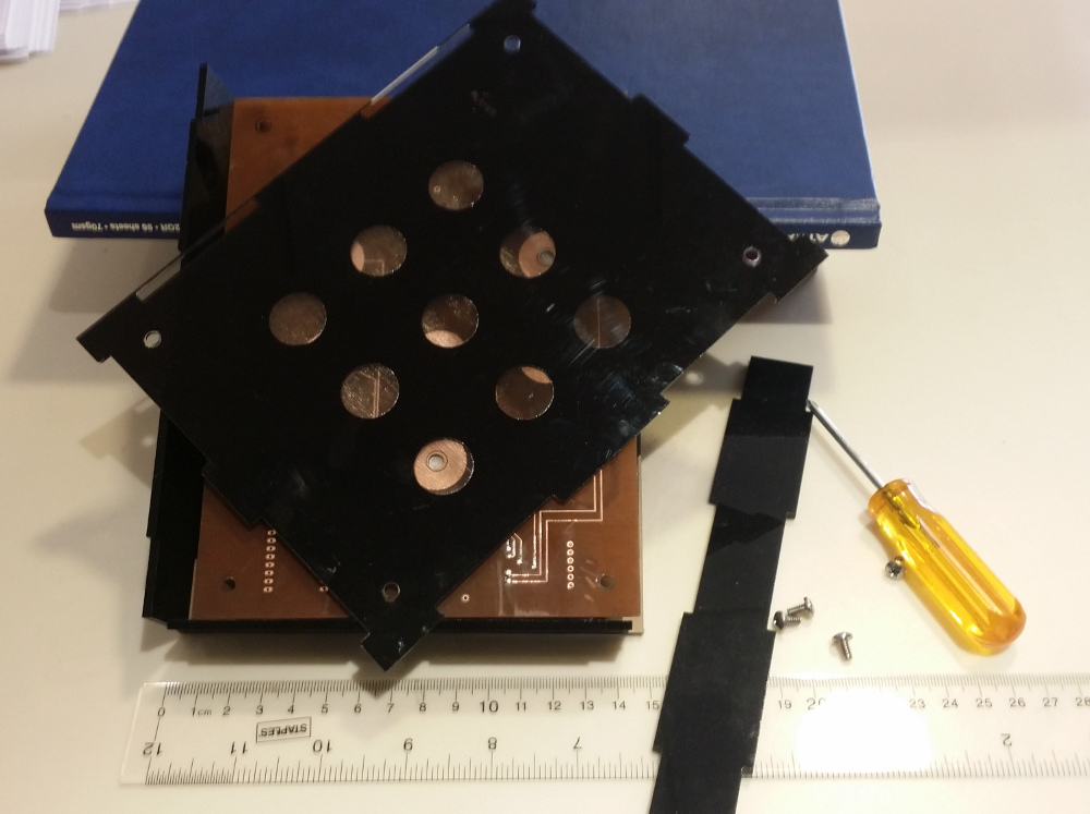
The top side of the box was made using transparent acrylic (1.5 mm thickness) and the interior side was covered with black latex paint. The laser cutter was also used to slightly carve the acrylic (removing the paint) at each button, hence, a finger is touching the acrylic over the copper button and not the copper. As the thickness of the acrylic can reduce the sensitivity it is important to use appropiate thickness and 1.5mm works OK but above 2mm, it starts to degrade the sensitivity requiring several attempts to get detected.
The system is powered out of a single cell Lithium battery (rechargeable) to provide 3.3 Volts for the microcontroller. An LM2621 is used as boost switching controller to produce 5 volts for the LPD8806 and LEDs power .
Below figure represents how the system works.

The main components are listed below:
-
Double sided PCB
-
Microcontroller:PIC24f16KA102
-
LEDs: Surface Mounted RGB LED 5050
-
LED Driver and controller: LPD8806
-
5 Volts Power : LM2621
-
Battery: UltraFire LC 14500 3.6V 900 mAh
-
Acrylic enclosing
The components were assembled on the PCB as shown below:

PCB top (components side) view

PCB top (components side) view
and below image shows all the parts before putting them together.

Putting parts together
Below video shows the game in action
Based on the comments, if there is interest, I can publish all the project details as gerber files for the pcb, firmware and box vector files.