Introduction
The LPD8806 PWM controller for RGB LEDs is well known to be used for color effects in long daisy chains of RGB leds. The LED strips are available online and sold by meter usually having 32 LEDs per meter which are controlled by 16 LPD8806s.
Most electronic applications require light indication of some sort not to mention the trivial power ON lamp. As single color lamp can bear two states of information. Several small embedded applications, apart from the ON/OFF states used to produce different blinking patterns in order to convey more information to the user. The RGB LEDs are multiplying the information that a single source of light can produce (which can also be increased using blinking patterns).
Application
The purpose of this article is to provide basic information on how to use these LED driver integrated circuits.
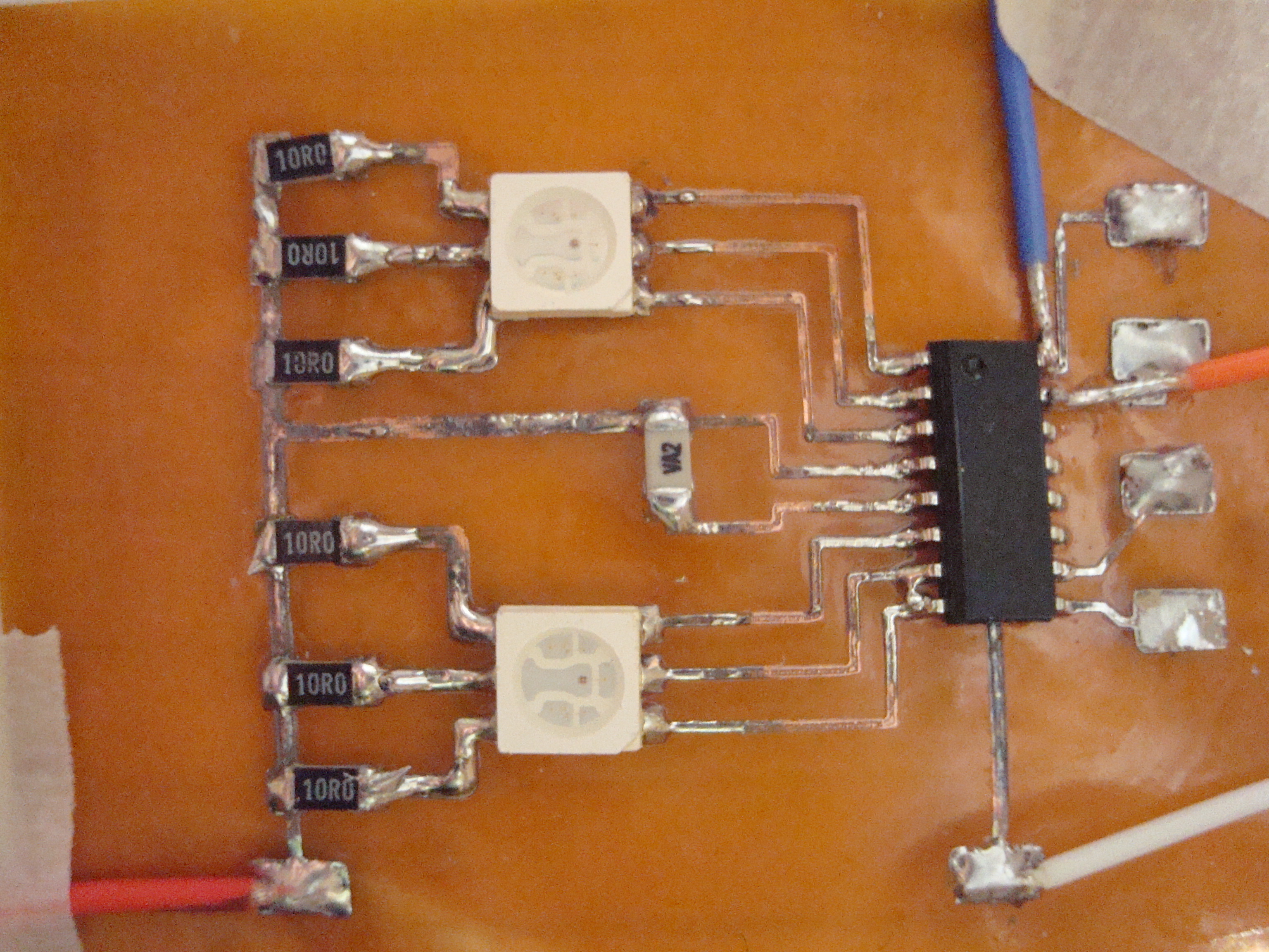
The LPD8806 can control 2 RGB LEDs receiving the status infotmation via SPI and requiring a minimum number
of external components just the the current limiting resistors and power filtering capacitor.

Basic LPD8806 Schematic
The LED's color are changed varying the pulse width (PWM) on each of the idividual subpixels primary color (RGB) The chip receives the PWM information as a 7 bit information from zero (LED turned OFF ) to 127 maximun brightness via SPI and it latches upon receiving the byte for each subpixel. Hence, three bytes are used to set the status of an individual RGB LED or pixel. These color bytes have all the most significant bit set at the value of 1, thus, the byte value for the brighness is from 128 to 255. This is so in order to allow an all zeroes byte to perform a particular operation.
As there is not official information on the communication protocol (the only availbale and poorly translated datasheet ), the control routines were developed by reverse engineering a commercial controller. The first case I know of was from LadyAda who developed and published a library for the Arduino on GitHub in 2011. At that time it was not clear the use of the zero bytes and the very first routines used to send a bunch of zeros in order to "prime" the strip; or the way to put the whole strip on a known initial state to start a sequence or particular color pattern display. Later on, users obtained more information from experimentation and trial an error testing and contributed in GitHub to reach what looks to be the final version and interpretation on what and how many zeroes are needed to be included in the communication stream dependinding on the total numbers of LEDs involved (more on this below).
Depending on the status of the pin PMOD (pixel mode) , the LPD8806 can control what is called a single pixel output (PMOD floating or tied to 5 Volts) where each RGB subpixels are controlled independently on each LED or using the same RGB information for both LEDs if PMOD is tied to GND.
Two SMD RGB LEds on a Piralux flexible PCB
Controlling the LEDs or pixels is a matter of sending an stream of bytes via SPI. For example, to control 1 pixel, 3 bytes must be sent being the first byte the data for the Green , the second the data for the RED and the last the data for the BLUE. The LPD8806 latches each subpixels on on the fly as the corresponding byte arrives. Any non zero byte arriving after the BLUE data is just passed thru for the next pixel. Following with the example, the fourth byte sent by the controller bringing the GREEN data for the second pixel will be passed to the 2 LED which is also connceted to the same LPD8806. Similarly , byte nymber 7 sent by the controller will completely pass thru the LPD8806 and is routed to the pin SDO (Data Out) if s second LPD8806 is used, its SDI pin must be tied to the SDO pin of the first one.
If the controller keeps sending non zero bytes the process will cpontinue for ever, once each pixel driver is latched, further data is just passed thru to the next in the chain. So here is where the zero byte use comes to the scene; a zero byte will just get the LEDs drivers ready to receive new data after being read by each driver . As per above description it may be inferred that, similarly, a zero byte will get every driver ready and then pass thru until the end of the chain. But this is not the case , users thru experiments verified that a zero byte can propagate only thru 32 pixels ( or 16 LDP8806 in PMOD = 1). If more than 32 pixels are chained, the controller must sent a second zero byte to account for pixels 33 to 64 and so on.
Software for AVR
As this article is based more on the use of the LPD8806 to control LED for user information on embedded devices or panels the zeroes quantity should not be an issue needing just 1 zero for most cases as it covers 32 LEDs . A single file library for AVR using a ATTiny45 can be downloaded from Github.
The chips can be ordered from multiple Chinese providers online via Aliexpress
